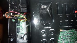
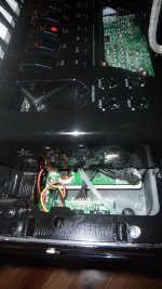
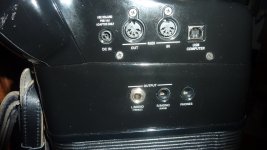
: I am having a problem with the connection to the L/MONO(TREBLE) Jack on my 8X. Also, the “plug to jack” physical connection is not very tight. With the slightest tug on the cord it falls out. Both problems are very annoying to me, especially when I am playing for a group audience. I always play my 8X connected to my Bose L1, since the sound is so much better with the Bose than with the internal speakers of the 8X. I was getting static/hum/popping in the Bose. I was using the L/MONO(TREBLE) Jack on the 8X. I switched to the R/MONO(BASS) jack. This Jack still had, what I thought, was not a very tight physical connection. The static/hum/popping problem was better--for a while. But in a few months the exact problem returned. I tried using DeoxIT D5, but no change/improvement. Maybe, because I always have the 8X output Jack connected to the Bose, the spring tension on the 8X Jack gets reduced. I don’t know. I only use one Jack. I do not use stereo, where I need both Jacks simultaneously.
My solution was to replace the L/MONO(TREBLE) Jack with a Switchcraft Conxall Jack that is much more substantial than the Jack that is mounted on the printed circuited board of the 8X. The Jack is a “through hole mount” that has nuts on both sides for a very secure mount to the 8X. The diameter of the Switchcraft Jack is larger than the diameter of the original Jack on the 8X. However, it does fit through the hole of the 8X case. I was worried about this. I would have drilled a larger hole on the 8X if I had to, but that was not necessary. I removed the L/MONO(TREBLE) Jack from the printed circuit board of the 8X and soldered wires to the printed circuit board to connect to the Switchcraft Jack.
NOTE: The ideal way to remove the Jack from the printed circuit board, would be to heat all three connection points at the same time. I don’t know how they do this when they manufacture the boards. Maybe there is a tool that will heat all three points at the same time. I only have one tip on my soldering iron. What I did was: heat one of the three points, lift the jack a little, go to the next point, lift it a little more, etc. I finally got it out. However, in the process, I damaged “one trace” on the circuit board that I finally repaired—it was a PAIN. If I had to do it again, I would start as I did, until I got the old Jack high enough to get “dikes” under the Jack and cut it off at the circuit board. Then I would go back, unsolder the cut wires from the circuit board, remove them, and solder new wires to solder to the Switchcraft Jack.
Below are pictures of my installation. The Switchcraft Jack has a very solid physical connection when you push it in. You have to grab the plug and pull hard to get it out. I like that. The electrical connections are perfect. I have used it for about a month now. It is “bullet proof”.
Attachments
Last edited:


