• If you haven't done so already, please add a location to your profile. This helps when people are trying to assist you, suggest resources, etc. Thanks (Click the "X" to the top right of this message to disable it)

hall effect switch?

Joined
Jul 2, 2020
Messages
8
Reaction score
2
Location
Northern Nevada
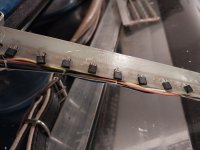
Hi. A bass key died due to one of the wires of the sensor being broken, looks like the magnet has been hitting it. I got the number off the sensor, and I can't find the same sensor on the internet. It's old, it's not a brand name midi system and the maker is deceased. I don't know how universal these accordion sensors are. I wonder if there's somebody that can match the sensor for me and sell me a couple, maybe the resistor too, I can solder it in. I took the bass section apart to get to this and I don't want to put it back together and ship it out only to be told they will need to install a complete new midi system. It seems simple enough and I just want to try replacing the one broken sensor. Thanks for any assistance or suggestions.
 

Attachments

  • 20240120_221400.jpg
    20240120_221400.jpg
    195.4 KB · Views: 27
I have no experience with Hall effect probes/switches in accordions. However those I’ve used in other equipment seem pretty robust. If the only problem is a wire lead is broken it may be easy to solder a piece of wire to replace it and it may work fine again without replacing the probe. The bigger question to me is why the magnet was hitting it. If due to some misalignment I’d examine and fix that first. If the probe its self is out of physical alignment perhaps it could be bent or even glued back into position.

Difficult to guess without the thing in hand. If you have an electronics wizard close they may be able do diagnose and fix in a heartbeat. There are geeks everywhere! If you have such things as “maker’s clubs” in your part of the world maybe knock on the door and ask there.
 
there's not much to 'em

usually they are soldered in place with a bit of leg length so you can bend it
a bit and adjust the trigger moment vs: key press

it is a specialized transistor more or less that acts as a switch when
a magnet comes close enough


try one of these or similar as a replacement

 
and yes you could probably repair the broken leg/lead, but you will need to
use a tweezer type heat sink between where you solder and the base of the
transistor body and precision apply the heat and solder to the joint
as briefly as possible
 
if you can connect the wires all back up you should be able to
test the repair before you re-assemble the whole dang thing
with a skinny, long cylindrical magnet and wave it near the repair and
along the other ones too
 
If the only problem is a wire lead is broken it may be easy to solder a piece of wire to replace it and it may work fine again without replacing the probe.

Solder is unlikely to make for a more robust joint than what you had before, and whatever bent the one pin bent the others as well. And we are not really talking expensive and/or irreplaceable parts here. So there seems comparatively little point in patching something up in an iffish manner that is supposed to be good for decades to come and that a customer may complain about.
 
I have no experience with Hall effect probes/switches in accordions. However those I’ve used in other equipment seem pretty robust. If the only problem is a wire lead is broken it may be easy to solder a piece of wire to replace it and it may work fine again without replacing the probe. The bigger question to me is why the magnet was hitting it. If due to some misalignment I’d examine and fix that first. If the probe its self is out of physical alignment perhaps it could be bent or even glued back into position.

Difficult to guess without the thing in hand. If you have an electronics wizard close they may be able do diagnose and fix in a heartbeat. There are geeks everywhere! If you have such things as “maker’s clubs” in your part of the world maybe knock on the door and ask there.
 
Hi, thanks for your thoughts. I already tried to solder it, but the break is right at the housing, I couldn't get solder onto it. I am going to try some conductive glue, but there's really nothing for it to attach to. The reason it was hitting is the board is in a tight space. Someone had put a little pad on another sensor, it was hitting too, so I'd like to have an extra sensor or two in case it fails someday. There's room to put a shim in to increase the gap so it won't touch.
 
accordionsrule: Seems to me like you're getting good advice here and good luck with this delicate soldering job. A small set of tweezers
might act as a suitable heatsink.
There's probably a simple answer: The defective component is identified with type number 3013U while those around it have, what looks like, type number 3120U. Is it possible that the 3013U has replaced the 3120U at some time and that a less than perfect fitting (soldering and/or alignment) has caused your present problem?
Good luck with the repair.
Thanks. Being a little more open minded about this code, I dropped the final U in my search and found a supplier of UGN3013. I think I'll call them Monday and see if they will tell me if the "U" matters and if they still carry them. The picture looks like it. I'll keep you posted.
 
good catch.. here is a data sheet for 3120


pin 1 is V+ 4.5 to 25 volts
pin 2 is ground
pin 3 is output

one would think any similar pin-out similar size and package
Hall sensor within that voltage tolerance will work as a substitute

here is a data sheet for 3113

 
The exact same thing happened to me with a Limex MPR3 system on the left hand side. It was apparently installed a little sloppy and magnets were lightly hitting two of the sensors as I played. After a few years, leads on these two sensors broke. (By this time, the person who had done the install was long out of business.)

As in your case, the sensors were discontinued components. As I did not have any ready replacements, I "borrowed" two sensors from the two highest notes on the right hand side and moved them to the left. I figured I could do without MIDI on the two highest treble notes until I could find proper replacements. This required very careful unsoldering and resoldering with a miniature soldering iron, so as to not damage the components or circuit boards.

Of course, you will also have to fix the mechanical problem of the magnets hitting the sensors.

As for replacing the two sensors I removed from the right-hand side, I first tried a newer component that seemed to have similar specs. However, it did not work. Limex uses analog sensors (generates a voltage proportional to the magnetic field) so that velocity can be measured. So the specs of the replacement are more critical than for a digital sensor. I eventually found exact replacements from a Limex dealer.

In your case, you have digital sensors (a simple on/off), and it is more likely the similar replacement components mentioned here will work. Probably, the most important thing to look at is that it is activated by a magnetic field of similar strength.
 
Last edited:
… I already tried to solder it, but the break is right at the housing, I couldn't get solder onto it. …
If the conductor break is right at the component housing it can be a difficult fix. I’ve done it two ways - one drill a tiny hole into the plastic directly adjacent to and parallel to the broken leg, then slide a length of tinned leg cut from some other component, apply flux, and solder while heating the longer piece. Generally works well. The other way is tricker and involves filing or grinding away some of the plastic casing to expose more of the leg for soldering. That can work too. The best, of course, is to replace the component!

Too bad you’re not local. Between myself and a friend we have bags of hall sensors.

I have silver-based conductive glue but can rarely get it to do what I want except when repairing traces on circuit boards

JKJ.
 
Thanks. Being a little more open minded about this code, I dropped the final U in my search and found a supplier of UGN3013. I think I'll call them Monday and see if they will tell me if the "U" matters and if they still carry them. The picture looks like it. I'll keep you posted.
The U very much matters. It is the form factor. There isn't actually something tangible called "UGN3013" according to the data sheets I read: it would have another letter following. Try figuring out which one.
 
The U very much matters. It is the form factor. There isn't actually something tangible called "UGN3013" according to the data sheets I read: it would have another letter following. Try figuring out which one.
Thanks for the heads up. Yes, it definitely matters.
 
If the conductor break is right at the component housing it can be a difficult fix. I’ve done it two ways - one drill a tiny hole into the plastic directly adjacent to and parallel to the broken leg, then slide a length of tinned leg cut from some other component, apply flux, and solder while heating the longer piece. Generally works well. The other way is tricker and involves filing or grinding away some of the plastic casing to expose more of the leg for soldering. That can work too. The best, of course, is to replace the component!

Too bad you’re not local. Between myself and a friend we have bags of hall sensors.

I have silver-based conductive glue but can rarely get it to do what I want except when repairing traces on circuit boards

JKJ.
Wow, you really have skill. Something else to try if all else fails. If I get this broken one swapped out, I may do the drill thing on it just for the experience.
 
good catch.. here is a data sheet for 3120


pin 1 is V+ 4.5 to 25 volts
pin 2 is ground
pin 3 is output

one would think any similar pin-out similar size and package
Hall sensor within that voltage tolerance will work as a substitute

here is a data sheet for 3113

They are identical, huh? It's good to see there are such wide voltage tolerances, it should make it easier to match.
 
Whoohoo, all fixed.
I ordered SPRAGUE UGN3013U from Electronic Expediters on Ebay, they make you buy ten so I have spares now. They are identical in size and shape to the ones in the accordion. But I am an inexperienced solderer and these are teeny, crowded parts, so to avoid a major operation first I tried to use solder glue. It worked, but lasted only a few days. I wasn't surprised.
Biggest trouble I had was getting the old switch off. The only solder wick I could find locally was too big, it was mucking the whole area up. So I switched to a tiny copper wire. I was afraid I had ruined the board with the big wick, it looked bad. But I got the new switch soldered in solidly, and it works great. So yay:-)
 
Back
Top