• If you haven't done so already, please add a location to your profile. This helps when people are trying to assist you, suggest resources, etc. Thanks (Click the "X" to the top right of this message to disable it)

Accordion Internal Microphone Issue - Repair

Thomas N

Well-known member
Joined
Jul 6, 2016
Messages
357
Reaction score
300
Location
Los Angeles
Gents - After 5 years of my Excelsior 960 internal microphone system not working I decided that today would be the day I take it all apart and trace the issue. I'm reasonably technically proficient, but on a low level.

I took all of the individual parts of the accordion meticulously apart and started tracing voltage from the 9v battery in the bass side of the accordion all the way through to the treble section.

Fortunately there is a separate connector at each accordion body part junction which makes troubleshooting simple.

My biggest fear was alleviated when I had 9v all the way to the treble side of the bellows connector. No rewiring through the bellows!

There was 9v present all the way to the 1/4" instrument connector and all the way to the treble grill. The issue therefore is with the circuitry on the treble grill.

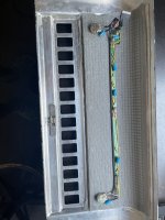
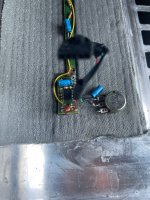
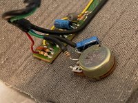
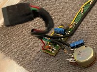
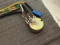
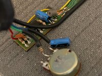
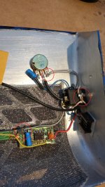
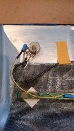
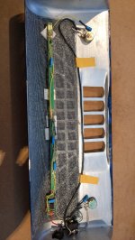
I have taken some pictures that I hope help. I immediately noticed that there is a wire missing on the connector shown in this picture. There appears to be residual solder on it which makes me think there was a wire there at some point. If it was a blank pin I wouldn't think the builder would put a drop of solder on it.

There is no wire available for connection, however. Unless it was a small jumper wire then I'm out of ideas. I tried to find pictures of this connector but was unsuccessful. Therefore I have nothing to compare it to. This system is around 20 years old.

I hope the pictures help. If anybody has any ideas it is most appreciated. Thank you!
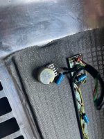

IMG_3722.jpegIMG_3723.jpegIMG_3724.jpeg
 
Also, to be clear in a somewhat muddy post, in the third and last picture, there is a verified 9v to the connector that plugs into the receptacle in this picture. So the breakdown is either in that black connector itself, or the circuitry on the board. Thanks!
 
I immediately noticed that there is a wire missing on the connector shown in this picture. There appears to be residual solder on it which makes me think there was a wire there at some point. If it was a blank pin I wouldn't think the builder would put a drop of solder on it.
It is hard to troubleshoot on a forum from a few photos, but here are a few thoughts...

When you say the microphones stopped working, can you be more specific? When you plug your accordion into your amplifier and turn up the volume, is it dead quiet, or is there some hiss or noise that seems to be generated by the accordion microphones?

I think the "connector" you refer to is the back of a potentiometer, probably a tone or volume control. The residual solder may be due to a wiring mistake by the installer that was later fixed, and probably does not indicate a missing wire. In any case, I doubt a missing wire would cause it to be completely silent.

You say "There was 9v present all the way to the 1/4" instrument connector". Do you mean in the vicinity of the instrument connector? There should not be 9v at the instrument connector itself. It should be audio only (very low voltage AC) with no DC voltage. Where is this instrument connector? I don't see one in the photos.

There are a lot of possibilities, even something as simple as a broken wire internally or externally (in your instrument cable). You traced the power wiring, but did you trace the audio wiring?

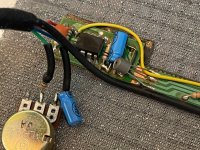
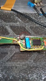
There appears to be an integrated circuit amplifier on the treble side, probably a simple op-amp circuit. After checking for broken wires, one thing I would try is to look up the datasheet of this IC (can you read the part number on it?), see where the power and output pins are, and use some test equipment to see if it is powered and generating any audio output. If you can't determine what specific part it is, chances are it has the same standard pinout as most op-amps.

That long yellow wire running from one end of the board to the other suggests this may have been modified by someone. If this connection was part of the original design, one would expect there to be a trace on the circuit board for it.

This should not be that hard to troubleshoot. If necessary, try to get assistance from someone who knows audio electronics.
 
Last edited:
It is hard to troubleshoot on a forum from a few photos, but here are a few thoughts...

When you say the microphones stopped working, can you be more specific? When you plug your accordion into your amplifier and turn up the volume, is it dead quiet, or is there some hiss or noise that seems to be generated by the accordion microphones?

I think the "connector" you refer to is the back of a potentiometer, probably a tone or volume control. The residual solder may be due to a wiring mistake by the installer that was later fixed, and probably does not indicate a missing wire. In any case, I doubt a missing wire would cause it to be completely silent.

You say "There was 9v present all the way to the 1/4" instrument connector". Do you mean in the vicinity of the instrument connector? There should not be 9v at the instrument connector itself. It should be audio only (very low voltage AC) with no DC voltage. Where is this instrument connector? I don't see one in the photos.

There are a lot of possibilities, even something as simple as a broken wire internally or externally (in your instrument cable). You traced the power wiring, but did you trace the audio wiring?

There appears to be an integrated circuit amplifier on the treble side, probably a simple op-amp circuit. After checking for broken wires, one thing I would try is to look up the datasheet of this IC (can you read the part number on it?), see where the power and output pins are, and use some test equipment to see if it is powered and generating any audio output. If you can't determine what specific part it is, chances are it has the same standard pinout as most op-amps.

That long yellow wire running from one end of the board to the other suggests this may have been modified by someone. If this connection was part of the original design, one would expect there to be a trace on the circuit board for it.

This should not be that hard to troubleshoot. If necessary, try to get assistance from someone who knows audio electronics.
I am very appreciative of your reply Steve! All excellent points. The microphone system was installed by the factory when I bought the accordion. It has not been modified.

There is no sound whatsoever from the instrument cable. I obviously tried different cables and different amps and none product any sound. There's no hiss, or pop when you plug it in.

I measure the voltage at the 1/4" plug hot lead and the nearby connector ground and there was 9v present so I know power is making its way to the instrument plug and nearby connector. You're right - those are two pots corresponding to the front grill bass and treble volumes.

And you're right about that long yellow wire! That is bizarre. One would think that would have been traced out on the circuit board instead. Really makes me wonder what kind of "system" this is!

My brother is an electronics genius, working with circuits for 50 years and always around a soldering iron. He could sniff this out quickly. Especially anything audio-related. He's quite a ways away from me and bringing an accordion, especially a massive Excelsior 960 is never an easy task.

I'll continue researching this and again, thank you for your thoughtful and helpful reply.
 
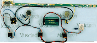
I found this photo of what appears to be an old MusicTech microphone system. It looks like it might be similar to yours.

1720047504436.png
It has that yellow wire. So maybe it is original. I don't see this wire in photos of their current microphone systems.

Also, each of the potentiometers has wires attached to all three terminals. As well as I can make it out from this fuzzy photo, my guess is that the one that is unconnected on your accordion should be attached to the ground of a shielded cable.

Are you really measuring 9 volts at the 1/4" plug hot lead? If so, I think that indicates a fault. There should be a capacitor that blocks any DC from going out to your amplifier. Maybe the capacitor is bad. Also, any DC voltage that a capacitor would be blocking would be about half the supply voltage, not the full 9v.

I hope your brother can help you figure this out!
 
Last edited:
Some sockets have a set of contacts for DC. My old excelsior was like that. Plugging in the cord to the amp also turns on the power to the mics and opamp. Take a good look at the socket and see if the contacts are dirty or perhaps not making contact as they should. Also it looks as if the shield of the coax should connect to that tab on the pot with the solder on it. Hard to tell from the photo. It is not normal to have only two of the tabs on a pot connected although sometimes the center and one end are connected when it is just used as a variable resistor.
 
Last edited:
Plugging in the cord to the amp also turns on the power to the mics and opamp.
Many guitar effects stomp boxes are like that. When you plug in the instrument cable, it turns the electronics on by connecting the normally unconnected negative terminal of the battery to the ground of the circuit. It would be reasonable for an accordion microphone to be designed that way. It saves having an on/off switch, but then you have to remember to unplug the cable when you are not using it to save the battery. However, that would not explain a measurement of 9v at the tip of the instrument plug, if that is what Thomas is reading.
 
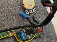
Thank you again! That MusicTech photo helped. I guess I should have noticed the name on the Circuit Board. Here are some clearer shots of the connector. There doesn't seem to be anything to connect to! Perhaps ground? I noticed on the other side of the circuit board they actually connected TO THE POT itself with a small jumper. Looks bush-league to me, but then again, so does the yellow wire.


IMG_3725.jpegIMG_3726.jpegIMG_3727.jpegIMG_3728.jpegIMG_3729.jpegIMG_3730.jpeg


The positive wire (red) connects to the last resistor. I am thinking there should be a short wire jumper between the other end of that resistor and the third terminal on the pot thereby supplying power to it all. Nothing to lose by trying. 9V stuff won't kill me! Thank you!
 
I am thinking there should be a short wire jumper between the other end of that resistor and the third terminal on the pot thereby supplying power to it all. Nothing to lose by trying.
The extra photos are helpful, but not sufficient to be certain -- but I will make some guesses. One guess is that the long yellow wire is carrying the treble audio to that pot at the other end, which is the treble volume control. I am guessing the other pot with the missing connection is the bass volume control. I think the missing connection probably needs to go to ground.

BTW, connecting a ground wire to the housing of the pot itself is not unusual. That is to provide some extra shielding and reduce hum.

It is a mystery why that wire is missing. Maybe it has been missing for a long time and this is only a red herring for your problems, as I don't think that missing ground wire would cause there to be no audio output. It would probably only affect the range of control you would have on the bass microphone volume.

I now see that the long yellow wire is optional. The long wire is needed only if the installer places the two volume controls at opposite ends of the grill. Some installations might put the controls next to each other.

Note the blue cylindrical components connected to one terminal of each pot. Those are the DC blocking capacitors that should prevent any DC from appearing at the 1/4" instrument jack. Measure the voltage at the pot terminal side of the capacitor, relative to ground. There should be little or no DC voltage.
 
Last edited:
these are obviously sennheiser elements

you note they have 3 legs, connected to the 3 traces on the circuitboard

only one of those legs should show 9 volts dc
one leg is ground
the third leg is the signal

the op amp.. you should be able to look it up from the number on it
to see the pinout.. the +power input leg needs to show 9 volts

those are the only 2 places you NEED to see 9 volts, where it is
necessary to bias/power the components.. other 9 volt testing
is only to verify the path of the 9 volts that it can get to where it is
needed, where it does it's work

you could take Caps schematic from the other current thread,
build a new op-amp section, strip everything off the circuit
board except the mic's, and fix it that way

the mics are among the best you can get
 
I don't have the solution but it is clear that the signal runs through the potmeters, and the missing wire (if there is one) would be a ground, in order to turn down that volume. So without anything connected to that third pin at the potmeter the worst that can happen is that one side of the accordion remains at "full blast" all the time.
Please note that this mic system will only work when a 1/4" plug is inserted. With nothing inserted there is no connection between the power supply (battery) ground and the electronics, When you insert the jack plug ground gets connected to the electronics. (And if the amp is on you will hear a loud bang which is normal.) So any real testing should always be done with a plug inserted.
 
...

the mics are among the best you can get
Yes, and they are placed sideways to avoid them from clipping. The mics are pretty close to the sound source and placing them sideways reduces the volume they pick up and at the same time avoid too much unevenness in sound pick-up between the notes close to a mic capsule and the notes further away.
 
Yes, and they are placed sideways to avoid them from clipping. The mics are pretty close to the sound source and placing them sideways reduces the volume they pick up and at the same time avoid too much unevenness in sound pick-up between the notes close to a mic capsule and the notes further away.
and Goedemorgen, good morning to you
 
I am thinking there should be a short wire jumper between the other end of that resistor and the third terminal on the pot thereby supplying power to it all. Nothing to lose by trying. 9V stuff won't kill me! Thank you!
Should be about right.

Check my 3-pin system. You're missing at least one path to ground (thus failing to power the system)
IMG_20240704_090713.jpg
IMG_20240704_090706.jpgIMG_20240704_091127.jpgIMG_20240704_090658.jpg
 
and Goedemorgen, good morning to you also

while point to point ground is always preferred, as your photo shows,
since he mentioned a hidden wire grounded to the body of the pot, and
the grill is aluminum, his system may have that path to complete the
power circuit

for both of you, you could see a small improvement in performance
if you replaced all the electrolytic coupling capacitors with tantalums..
that is to say all the caps except the one across the op-amp
which i think it's purpose is to buffer the voltage
 
I’ve never examined that or a similar circuit but I have repaired many things over the years. If not well familiar with the concepts, yes, best to get help from someone who is. The circuit in the photo looks quite simple compared to many.

That said, I approach such things by first examining closely for bad connections (e.g. loose connections or “cold” solder joints). For a simple circuit like this I draw out a schematic of all the wiring and components, identifying each component and it’s value. I trace the ground and power connections and if they make sense, for a circuit with audio or other signals I trace the signals. Tools needed are a multimeter and an oscilloscope. My oscilloscope was quite expensive but I see many on Amazon now that are quite cheap. Once you have the circuit diagram and assure the proper voltage is getting to where it’s needed it’s usually straightforward to follow the signal path from the source (in this case the microphone, and determine when the signal stops. This can point to a bad connection or component. Note that some discrete components (e.g. resistors, capacitors, diodes, and potentiometers) may have to be temporarily unsoldered for proper testing - for a pot apply an appropriate voltage across the resistive element an monitor the voltage on the wiper for correctness. Note that a pot with one end unconnected is simply a variable resistor but one with all three terminals connected often functions as a variable voltage or signal level source. ICs can be particularly difficult to test since you need the function and specs on the pinouts pinouts. Many are “off-the-shelf” and can be looked up by the number printed on the too. (I can’t determine the details from the photos.) If it’s a common one it is often easier to simply substitute a known working chip. Note that it is possible to destroy a good component (such as an IC or diode by testing improperly.

All that said, unless you really want to do it yourself by far the best thing is to take it to someone with experience. It doesn’t have to be someone with accordion electronics experience but anyone with experience with simple low-voltage audio circuits like this one could probably fix it easily. Without some experience there is a lot of guessing, some which might even damage an otherwise good component. Without experience and proper tools it may be better to run away.

Just my 2 cents

JKJ
 
Thank you all! It was nice to wake up this morning with some coffee and read these replies. Thank you for the pictures Jozz! It helps so much to see another working system.

Paul:

Please note that this mic system will only work when a 1/4" plug is inserted. With nothing inserted there is no connection between the power supply (battery) ground and the electronics, When you insert the jack plug ground gets connected to the electronics.

I knew this from tracing the path of the voltage, yet did not do it! This is a really valuable point. I checked the voltage at the instrument port and seeing 9V I assumed all was well and the issue was in the connection from that connector to the connector on the grill circuit board. But without connecting the instrument cable and completing the circuit any checking on the circuit board would not show any voltage! That's my first task this morning, and then I'll move forward with the other excellent suggestions supplied here.

Again, thank you all!
 
just as an aside, it became my habit on all the self-made active/powered
mic systems and Master sennheiser (america kit) units i have installed over
the decades, that i in fact add an actual on-off swirch and eliminate the
jack/power scheme entirely. Jack switches can even fail just from oxidation
as the actual contact area on a round barrel against a flat spung contact
point is actually infinitisimally tiny, and relies completely on pressure
which some jacks get wobbly and fatigued with age

i also add a low power LED in a discreet place/angle

i simply decided i needed to KNOW for SURE when a battery was depleted,
and i need the re-inforcement in a loud environment that my Mics are "live"

while i sacrifice a bit of battery life and real-estate to have this, for me it is
a no-brainer kind of tradeoff, and i even have sacrificed the hidden battery for a
metal clip on the outside of the grill a time or two

i even went with a surface mount right angle Shure XLR instead of the 1/4" on the bottom
for my Rock n Roll accordion back in the 80's

so don't be afraid to customize this kind of stuff to suit your habits and style
 
Gents -

It works now! I can't thank you all enough for all of the incredible advice and assistance.

I ended up connecting the front grill to the body and inserting a 1/4" instrument cable and reading voltage. Yep, it now showed as supplied to the circuit board. So Paul's advice (along with another recommendation) was spot-on. No power without that instrument cable plugged in.

So with power to the board I then went to cleaning all contacts and checking all wires. The 1/4" jack was loose. I cleaned it and used a different, much lighter instrument cable which would pull less on the connecting jack.

I immediately heard pops and cracks and knew it was working. After a few adjustments everything worked perfectly fine. I ended up playing for an hour because it was the first time in years that I didn't have to fight the weight of the instrument and could allow the amp to do the heavy lifting.

I ended up pouring sweat onto the accordion because of the sheer physicality difference in playing it versus my FR-8X. I only stopped playing due to the sweat! That Magnante light and fast keyboard is worlds apart from the Fatar synth-action FR-8X. Runs are so much cleaner and faster. I felt like I just bought a brand new $18K Bugari acoustic.

I also learned a lot about how this accordion was made and the attention to detail the builder(s) used. Everything is individually cut and fitted, the mechanisms are intricate. Every drilled hole, the grill mute, each screw meticulously constructed. It gave me a lot more respect for the builders of these instruments. It also scared the hell out of me if something breaks.

Thanks for helping me get my 960 back!
 
just as an aside, it became my habit on all the self-made active/powered
mic systems and Master sennheiser (america kit) units i have installed over
the decades, that i in fact add an actual on-off swirch and eliminate the
jack/power scheme entirely. Jack switches can even fail just from oxidation
as the actual contact area on a round barrel against a flat spung contact
point is actually infinitisimally tiny, and relies completely on pressure
which some jacks get wobbly and fatigued with age

i also add a low power LED in a discreet place/angle

i simply decided i needed to KNOW for SURE when a battery was depleted,
and i need the re-inforcement in a loud environment that my Mics are "live"

while i sacrifice a bit of battery life and real-estate to have this, for me it is
a no-brainer kind of tradeoff, and i even have sacrificed the hidden battery for a
metal clip on the outside of the grill a time or two

i even went with a surface mount right angle Shure XLR instead of the 1/4" on the bottom
for my Rock n Roll accordion back in the 80's

so don't be afraid to customize this kind of stuff to suit your habits and style
We're almost on the same page here.
One of the first modifications I made on my Microvox mic systems was to have power only controlled by the on/off switch (embedded in the volume potmeter). and not by inserting the plug. Deteriorating contact through the plug has caused too many cracks and noise for comfort.
I'm not a fan of the power LED though, especially after seeing accordions with the blue LED smack in the center of the grille with Harmonik mics. What I have done to be more certain about having sufficient juice in the battery is replace the 9V battery by 6 1.5V AA batteries. (Only works if there is room for them). These will easily last me a year, and I also sacrifice a bit of battery life by replacing them once a year.
I also use an angled jack plug (not XLR but 1/4") with the cable held firmly in place by the secured bellow strap. So far no problems with the contact or with accidental unplugging of the cable.
 
Back
Top